Photoemission Laboratory Infrastructure
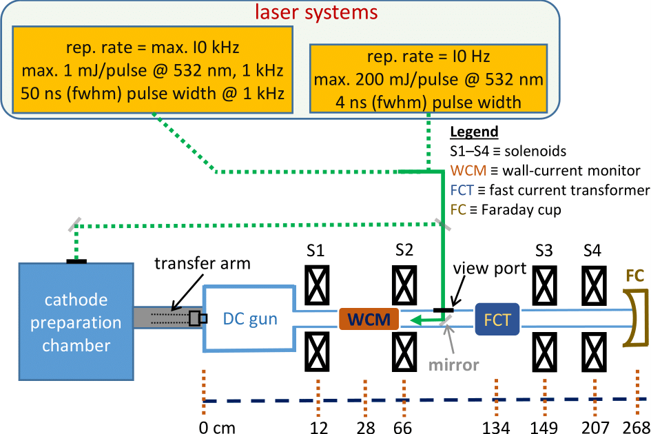
The Photoemission Laboratory includes a photocathode preparation chamber equipped with a physical vapor deposition system originally designed for two-element deposition, and a test DC electron gun beamline for photocathode characterization as shown in Fig. 1. A transfer arm mechanism allows for a quick photocathode transfer from the preparation chamber to the DC gun without vacuum intervention. The lab is equipped with two commercial flash-lamp pumped Q-switched Nd:YAG laser systems which deliver up to 10 kHz (quantronix model 532 DP-1) and 10 Hz (spectron model SL802) repetition rate pulse trains, respectively. Either laser system can generate laser pulses of wavelength 532 nm via a single stage second-harmonic frequency up-conversion of the source 1064 nm IR using a DCDA crystal, or 266 nm UV pulses via an additional second-harmonic stage using a KDP crystal; Fig. 1 shows some additional laser pulse specifications.
The operational voltage of the DC gun is 65 kV. For proper transport of the electron beam that exits the gun, four solenoidal magnets S1–S4 are employed along the beamline for weak focusing, as shown in Fig. 1. A wall-current monitor (WCM) with an acceptance bandwidth from 1 MHz to 10 GHz located between S1 and S2 (see Fig. 1) records the generated electron beam current for bunches with durations on the order of 10 ns. For longer bunches, a fast current transformer (FCT) or a Faraday cup (FC) located at the end of the beamline is utilized for beam charge measurements. A residual gas analyzer (RGA) system is installed in the preparation chamber in order to monitor for any gaseous contaminants.
The photocathode preparation chamber is designed for co-deposition methods on the grounds of historical success of such methods in producing better QE and lifetime Cs-Te photocathodes at the facility, in comparison to the more traditional sequential-layered deposition methods. The chamber contains three dispensers corresponding to different elements as shown in Fig. 2(b). Each dispenser bears a dedicated power supply for an independent control of the associated evaporation rate via resistive heating. There are two deposition-thickness monitors (quartz microbalances), as shown in Fig. 2(a). The independent thickness-monitoring is achieved by a pair of masks that shield the vapor(s) of one set of dispensers from the other dispenser and vice versa. The preparation chamber can accommodate a maximum of three cathode plugs at any given time including two storage positions.
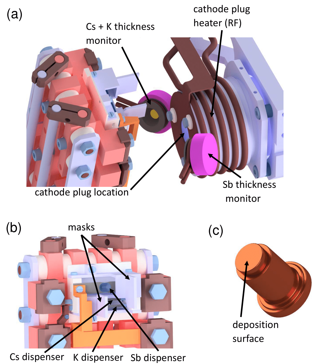
The 19-mm diameter top surface of an oxygen-free electronic (OFE) grade copper cathode plug (Fig. 2(c)) with oxygen content <5 × 10⁻⁴% serves as the substrate. The cathode plug is inserted in a receptacle that is equipped with an RF heater that facilitates control of the substrate temperature between room temperature and 200 ◦C as measured by a thermocouple. The thermocouple is in thermal contact with the receptacle whose temperature is assumed to represent the temperature of the cathode plug. During a deposition process, the generated photoelectron current can be monitored in real time for QE optimization with a circular anode biased at 1 kV with respect to the cathode potential. A shutter located between the dispensers and the substrate allows for a precise control of the start and stop times of the deposition process onto the substrate. The remote control, monitoring and data acquisition of critical parameters like dispenser currents, deposition thicknesses and photocurrent is achieved via the equipped software interfaces. A motorized mirror located outside of the beamline allows for an automated QE scanning at discrete planar points on the photocathode surface.
XPS Laboratory Infrastructure
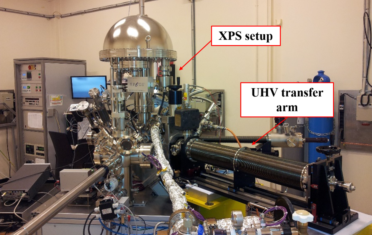
A commercial ultra-high vacuum (UHV) system (SPECS Surface Nano Analysis GmbH, Berlin, Germany; see Fig. 3) is utilized for X-ray Photoelectron Spectroscopy (XPS) characterization of photocathodes. The system consists of a hemispherical electron energy analyzer with 9 channeltrons (Phoibos 150) and a monochromated Al-Kα X-ray source (XR50M, hν = 1486.7 eV). While the base pressure of the system is below 2 × 10⁻¹⁰ mbar, the pressure is maintained at 3.5×10⁻¹⁰ mbar during insertion of a given photocathode sample via a transfer vessel and while performing XPS measurements. The energy scale of the analyzer is regularly calibrated using sputter-cleaned polycrystalline Cu, Ag, and Au foils and characterizing the binding energy (BE) of the Cu2p3/2, Ag3d5/2 and Au4f7/2 core levels as well as the Fermi edge.
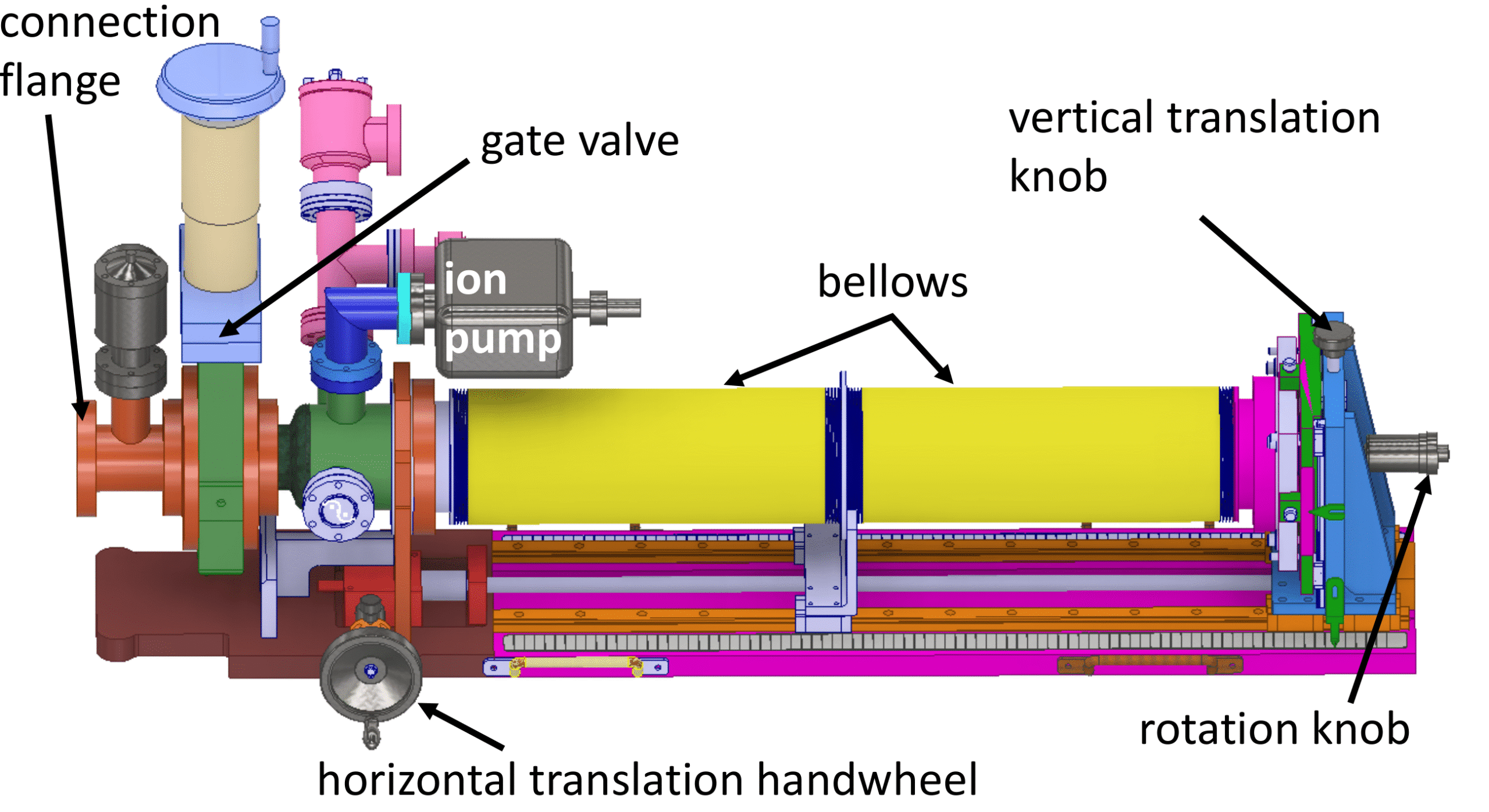
The transfer vessel (a 3D model shown in Fig. 4) is equipped with a Ti-Zr-V non-evaporable getter (NEG) sputtered coating which allows for the transfer and transport of a photocathode, via a transfer arm, between the preparation chamber and the XPS machine under UHV conditions. The pressure in the NEG chamber (the bellows section in Fig. 4) of the vessel is always maintained below 1×10⁻¹¹ mbar with the help of an ion pump which is separated from the connection flange with a gate valve, as shown in Fig. 4. Transfer of a photocathode into or from the preparation chamber or the XPS machine is achieved by first connecting and vacuum-sealing the connection flange to the given instrument, followed by baking the connection section at 150 ◦C for about two days under vacuum-pumping provided by an external turbo pump until the vacuum pressure is ∼1 × 10⁻⁹ mbar. Subsequently, the gate valves linking the given instrument and the NEG chamber are opened allowing for photocathode transfer. The transfer arm of the transfer vessel holds the cathode plug during transport. The cathode plug remains on the transfer arm when introduced into the XPS analysis chamber. Using the integrated x-y-z manipulation of the transfer system, the arm is extended to the desired position and the sample surface is leveled to match the calibrated joint focus point of the electron analyzer and the X-ray source to maximize XPS intensity, which is in parallel recorded continuously.