Laser Infrastructure: CLEAR
CERN Linear Electron Accelerator for Research (CLEAR) is a stand-alone user facility, with the following goals: Accelerator R&D, support of high-gradient acceleration concepts in CERN’s interest, creation of a test-bench for beam instrumentation, boosting collaboration with other science fields (such as Xray FELs, medical, space and industrial communities), and maintaining training capabilities for the next generation of accelerator scientists and engineers. The machine parameters of CLEAR electron linac can be found elsewhere. On this page, the CLEAR photoemission drive laser system is described.
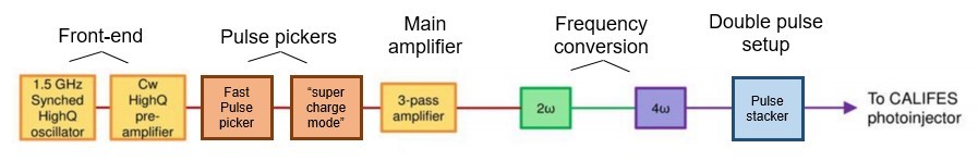
The CLEAR laser system is composed of a front-end comprising of an oscillator and a pre-amplifier, a main amplifier and a frequency quadrupling stage as depicted in Fig. 1. The UV laser source is centered at 262 nm, to operate Cs-Te photocathodes utilized by the CLEAR linac, with laser pulse energy of >370 nJ/pulse (although laser energies of up to 1.5 µJ per single pulse on the photocathode surface have been demonstrated).
The CLEAR laser system’s parameters are given in the following table.
Laser parameter | Value range |
Energy onto the cathode [µJ/bunch] | Up to 1.5 |
Intensity stability rms | <1.5% |
Spot diameter on the cathode σ [mm] | 0.8-1.5 |
Pointing stability onto the cathode rms | <0.2 |
Wavelength [nm] | 262 |
Micro-bunch length FWHM [ps] | 4.7 |
Micro-bunching frequency [GHz] | 1.5 |
Micro-bunch train length | 1-180 |
Micro-bunch train length (supercharge mode) | 1-1500 |
Repetition rate [Hz] | 0.833 to 5 |
Oscillator: The seed pulses are produced by a diode-pumped Nd:YLF mode-locked oscillator at a repetition rate of 1.5 GHz with an average power of ∼300 mW at 1047 nm. The output pulse duration is ∼ 5 ps. The synchronization with the RF reference is obtained at the laser oscillator level. The repetition rate of the oscillator is compared to the RF reference, and a PLL acts on the laser cavity end-mirror through a fast piezo-controller in order to stabilize it (with a feedback loop bandwidth of up to several 10 kHz). After initial commissioning, a time jitter of <100fs rms has been measured [8] . However, during day to day operations, the estimated value for the time jitter is of the order of 300 fs standard deviation.
Pre-amplifier: The oscillator output pulses are firstly amplified by a Nd:YLF pre-amplifier in order to boost the available average power up to ∼ 10 W. The pulses delivered by the pre-amplifier have the same temporal characteristics (5.3ps pulse duration at 1047nm) as the oscillator pulses. The tuning of the wavelength of the pumping diodes of the pre-amplifier is performed by temperature adjustment of its chiller with 0.1K increments.
Pulse picker system: The pulse picking system of the CLEAR laser is composed by three different pulse picking systems as depicted in Fig. 2. The first pulse picker system, a commercial pulse picker from Leysop Ltd., consists in a fixed width window with duration of 1 µs, which main purpose is to limit the input average power into the main amplifier. This pulse picker is triggered by a delay generator controlled from the CLEAR laser lab, although externally triggered by the CLEAR facility timing system.
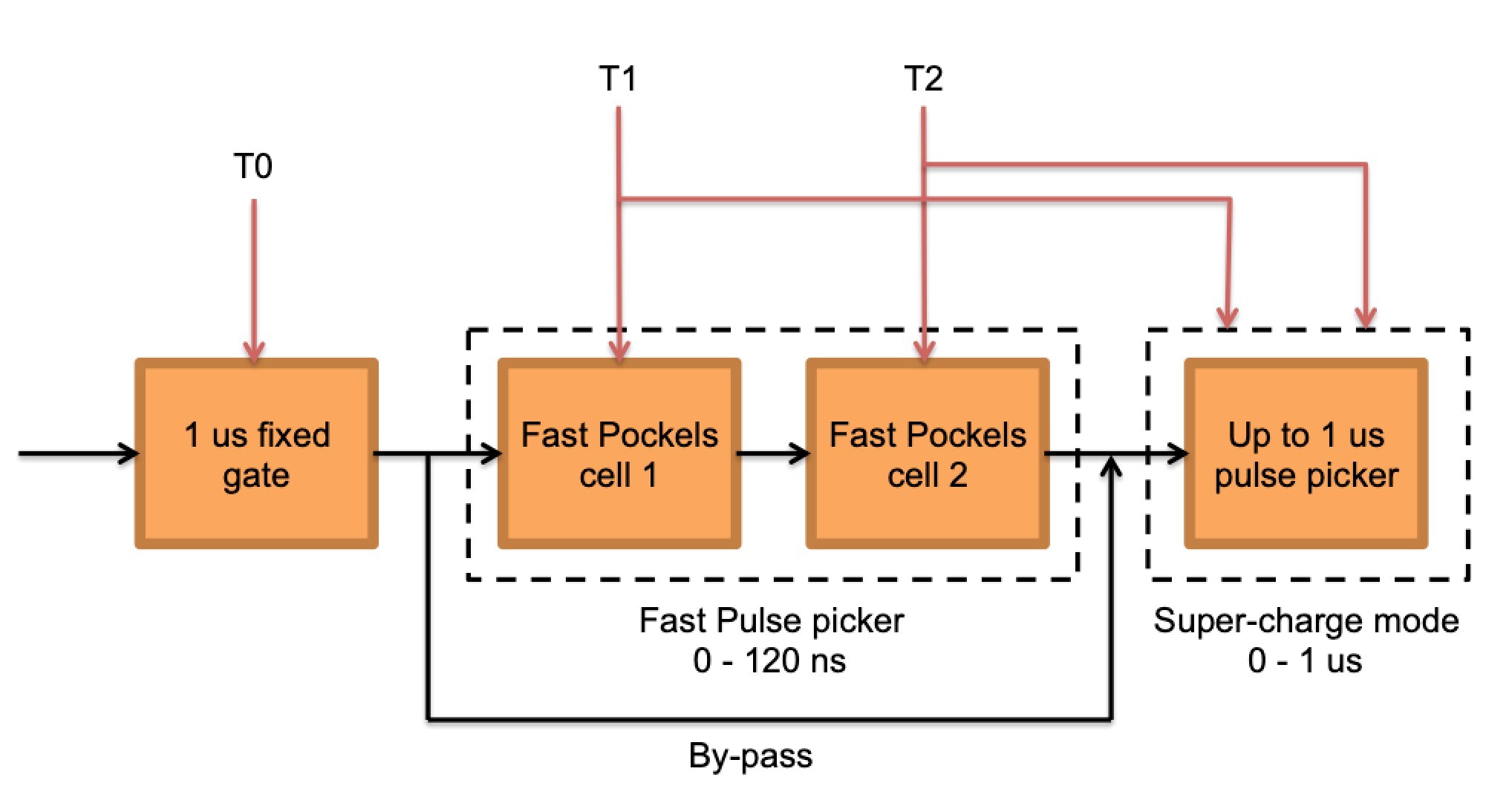
The second pulse picker system, commonly known as ‘fast pulse picker’, was designed for allowing discrimination of single pulses from the laser front-end at 1.5 GHz repetition rate (achieved with a pulse picker with rise-time <400 ps). The maximum pulse train duration is limited to 120 ns, which is the duration of the HV signal to the either Pockels cell. A third pulse picker (super-charge mode) has been placed at the output of the fast pulse picker to enable the production of longer pulse trains of up to 1 µs. It is to be noted that the super-charge mode picker is operated after bypassing the fast picker as shown in Fig. 2.
Main amplifier: The output from the pulse picker system is image-relayed onto the main amplifier head by employing a 4f telescope. An isolator is placed before the amplifier to avoid potential back-reflections. The beam is then passed 3 times through the gain media in order to amplify it. A schematic of the amplifier is depicted in Fig. 3.
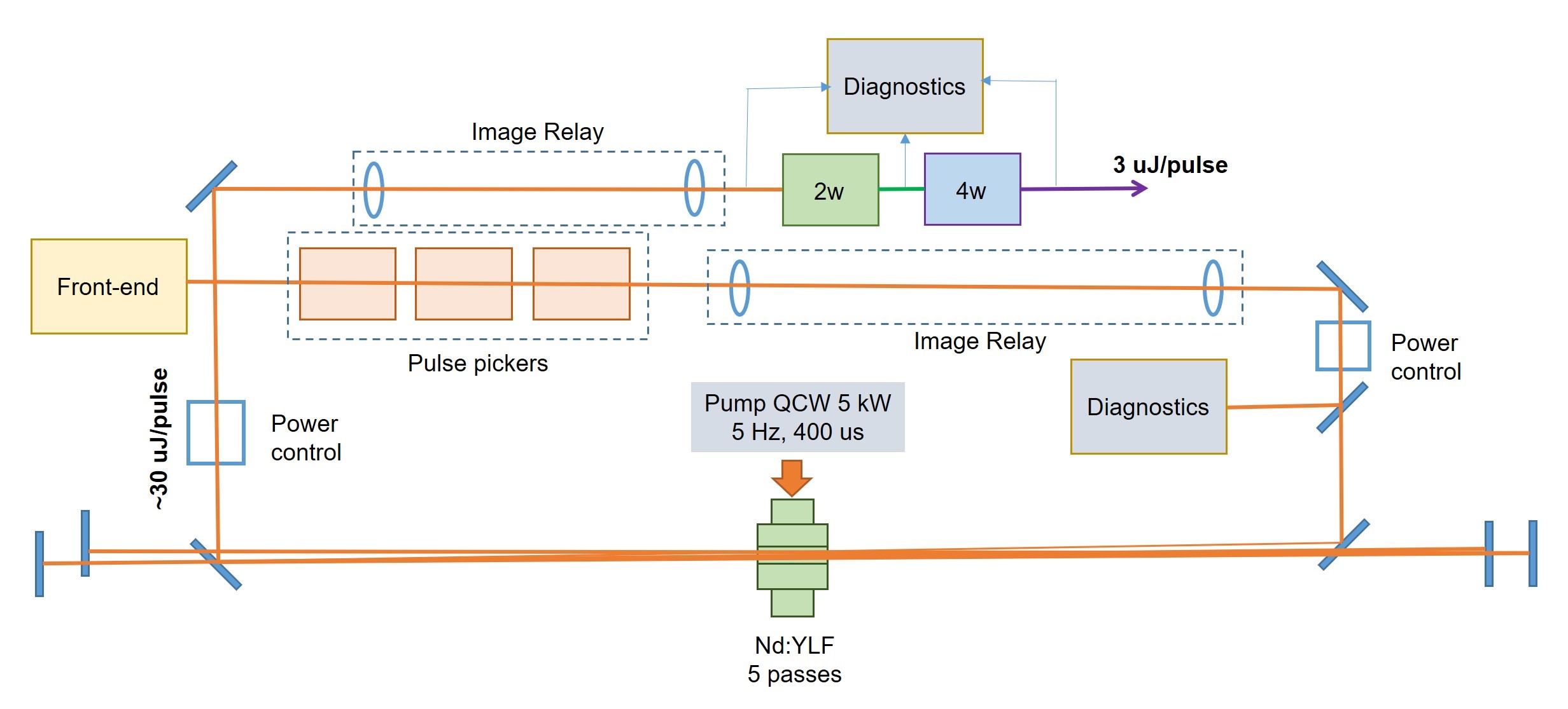
The amplifier is comprised of a 44 mm long, 4 mm diameter Nd:YLF rod (with an Nd concentration of 0.8%), housed in a water cooled copper mount. The rod is side pumped by Dilas QCW diodes (400 µs pulses with 5 kW average power during the pulse) at a maximum repetition rate of 5 Hz. Under these conditions, the single pass gain is approximately 8, whereas the gain after 3 passes is of the order of 103. After amplification, the pulses have an energy of approximately 30 µJ at 1047 nm. Power control systems are implemented at the input and output of the amplifier.
Frequency conversion to UV: Frequency conversion is performed with standard non-linear optical crystals. For the second harmonic generation (from 1047 nm to 527 nm), type II conversion in a 10-mm long KTP crystal yields a conversion efficiency of 35%. The spot size in the crystal is approximately 3 mm in diameter (1/e2) with vertical polarization. The output at 527 nm is horizontally polarized with a maximum pulse energy of 15 µJ. Conversion to the UV is performed in a 12-mm long BBO (type I phase matching), utilizing directly the output from the KTP crystal (similar beam diameter of around 3 mm). The typical efficiency of the process is approximately 30%, bringing the overall efficiency to 10% from IR to UV. A slightly different conversion efficiency was measured for long trains of 100 ns, where the existence of short life-time (ns to ps) color centers in the BBO crystal may play a role.
Double pulse generator: The double pulse generation at CLEAR is based on a common concept of pulse stacking. The pulse stacking technique involves the production of replicas of a given pulse (train) via splitting and recombining of a single pulse (train). As the delay between replicas is increased beyond the train duration, multiple laser bunch trains can be generated within the same RF macro pulse cycle.
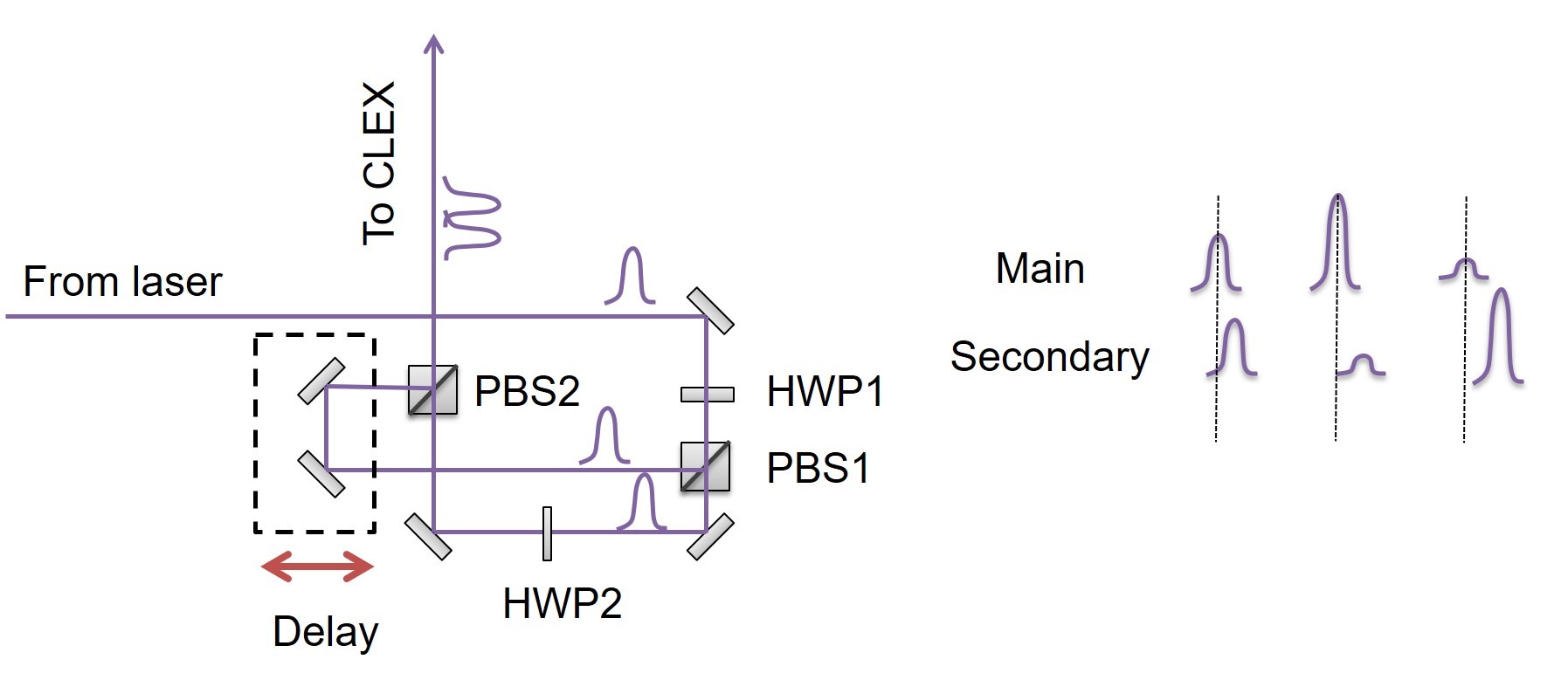
For splitting and recombining the UV pulses, a modified Mach-Zender interferometer was used (see Fig. 4). The laser pulse is first divided into two by a polarizing beam splitter (PBS1) so that the P-polarized beam goes straight and the S-polarized beam is reflected laterally. The ratio of powers of the beams is controlled by the half-waveplate HWP1. Each of the beams (P and S polarized) hit the corresponding sets of mirrors and then they are recombined by another polarizing beam splitter cube (PBS2). One set of mirrors was positioned on a movable platform so that the relative delay between the two beams can be adjusted. A second half-wave plate (HWP2) provides adjustment of the intensity of the main (non-delayed) beam.